Extravehicular Mobility Unit (EMU)
Miscellaneous parts
Umbilical
Connectors
Here I will attempt to make sense of the
layout of the suit umbilical connectors!
These were part of the Torso
Limb Suit Assembly (TLSA), a sub-assembly of
the Pressure Garment Assembly
(PGA).
The layout of the umbilical connectors changed
from the A-7L and the A-7LB suits.
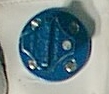
To start, blue umbilical
connectors bring something IN to the suit.
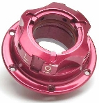
Red ones take
something OUT of the suit. Having said that, here are some pictures:

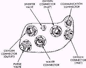

Left - Your map to the umbilical connectors:
A7-L on top and A7-LB on bottom
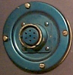
Center - NASA Diagram of A7-LB umbilical connectors
Right - CMP Unbilical Connectors for SIM
Bay EVA
The Relief Valve was supposed to be used if and
when the OPS was ever activated. By opening a small valve which would
essentially create a hole in the suit, a pressure gradient was created
which would cause the oxygen from the OPS to flow into the suit.
Original photo used in bottom of above graphic courtesy
Kipp Teague's
Project Apollo Archive


