 Twenty five years ago on 14 May 1973, the United States launched its first (and so far only) space station. It was not the world's first - that honour went to the Soviet Union's Salyut 1 space station. Skylab played host to three crews of astronauts which were launched in Apollo Command and Service Modules (CSM) left over from the Apollo program.
Skylab itself was initially conceived as a spare Saturn V third stage which would be drained of propellant after reaching orbit and outfitted by visiting astronauts prior to commencing scientific research. However this idea was later revised so that all internal fittings, equipment etc, were installed on the ground. This third stage was to become known as the Orbiting Workshop (OWS). Attached to the forward end of the OWS was the Airlock and Multiple Docking Adapter (MDA) where the Apollo CSMs would dock. Supported on a complex truss structure was the Apollo Telecope Mount (ATM). This was placed longitudinally at launch and was rotated around 90 degrees, by means of a pulley system, upon reaching orbit. The ATM held the solar observatory from which a total of 182,842 photographs of the Sun were taken by the three crews. Skylab was to be powered by two large wing like solar arrays and four smaller ones mounted on the solar observatory.
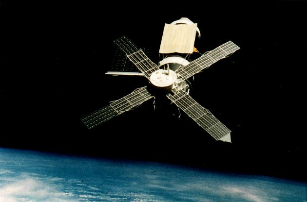
However shortly after launch, aerodynamic forces ripped off the micrometeoroid shield, taking with it one of the large solar wing arrays and trapping the other. Without the micrometeoroid shield which also acted as a sun shade, internal temperatures rose dramatically. It quickly became obvious that the first crew could not take up residence without some sort of remedial action.
NASA delayed the launch for ten days of the first crew in order to plan and practice the repair procedure. On 25 May Commander Pete Conrad and his crew of Joe Kerwin and Paul Weitz launched to the space station. The crew were subsequently able to free the trapped solar array and deploy a parasol sun shade to lower the internal temperature. They went on to complete 28 days aboard the orbiting station. The second crew was comprised of Commander Al Bean, Owen Garriott and Jack Lousma. They completed 56 days of experiments and erected a second sun shade over the first one which had not deployed properly. The final crew of Commander Gerry Carr, Bill Pogue and Ed Gibson went on to set a then space endurance record of 84 days. This remained the longest flight of a US astronaut until recently when Norman Thagard remained in space for 115 days, the majority of which were spent aboard the Mir space station.
It had originally been intended that the space shuttle would dock with Skylab and re-boost it to a higher orbit where more astronauts could make use of its facilities. Unfortunately the space shuttle program did not proceed as quickly as anticipated and Skylab gradually lost altitude and drifted towards re-entry. It was also unfortunate that the Solar Maximum 11 year cycle coincided with this time. This caused the Earth's atmosphere to expand to tenuously reach the orbit of Skylab and further slow the station in orbit thus accelerating the rate of descent. In 1978 Skylab re-entered over Western Australia - parts of which survived to impact in the Outback.
I obtained a 1m length of 88mm diameter tubing from Plastruct which would form the body of the OWS and which was cut to a length of 211mm. When the micrometeoroid shield tore off, the OWS was left with no exterior skin on that section and mirror-like gold foil exposed underneath. Using normal 20thou plastic card and Evergreen Scale Models grooved plastic card (No. 4527) obtained from my nearest model railway stockist, the areas forward and aft of the missing shield were built up to a diameter of 91mm (see fig 1 for details). This left a 97mm long mid section running around the circumference of the OWS at a slightly lower level than the rest of the OWS. A tunnel conduit runs the length of the starboard side.
| Click on the image for the full-sized drawing. |

|
The MDA was constructed from a 42mm diameter tube, 110mm in length and inserted within a circular piece of plastic which would act like a plug within the OWS tube. The MDA protruded from this disc by 105mm. At the forward end of the MDA is the primary (axial) docking port which is 15mm in diameter and which is centred within a shallow cone end section. This was made from a cut down 1/72 space shuttle Spacelab end cone. On the underside of the MDA is located a backup (radial) docking port. Forward of this port is an oblong box which houses an infrared spectrometer and just aft of the port is an instrument casing covered with chrome Bare Metal Foil which is a multispectral scanner. On the forward port side of the MDA is a series of raised panels, some 1mm in height. Figure 2 shows the MDA.
| Click on the image for the full-sized drawing. |

|
Inside the forward end of the OWS I superglued a 15mm wide strip of 20thou plastic card. The MDA/circular plug was inserted from the rear until it rested neatly against the inside lip. This ensures that the MDA is protruding from the OWS the correct distance (see photos). The Fixed Airlock Shroud was the next thing to be added. This is a truncated cone shape which adapts the OWS diameter to the MDA diameter and was constructed from sections of plastic card to get the rough shape and then large amounts of filler were added to refine the shape. The shroud has to be very secure and sturdy as it will be required to support the ATM truss structure. There is an opening, covering 90 degrees on the top starboard side of the shroud which allowed the crew to egress and ingress the airlock (see fig 1). As it is quite large on a model of this scale, the opening was detailed with bits and pieces from the spares box. The MDA and Airlock Shroud were sprayed matt white with the MDA subsequently having a pattern of black panels sprayed on the underside and forward port side (see photos). The Airlock Shroud opening was painted matt black. The MDA nose section is also black but with a thin white band running around the circumference of the cone section. Finally a small US flag decal was placed just above and to the left of the axial docking port.
At the rear of the OWS is a hemispherical bulkhead 12mm deep and which, once inserted into the OWS protrudes by 8mm. This was covered with chocolate foil and painted a dull dark copper colour. Directly attached to this is a torus shape which contained nitrogen bottles. This was constructed by initially cutting out a 42mm diameter plastic card disk. This was used as a template to draw the next plastic disk in a series of ever increasing diameter disks. By using this method each successive disk is slightly bigger than the previous. This is continued until the last circle reaches 60mm in diameter. The concentric circles were glued together forming a truncated cone shape (see photo). A second indentical shape was made and the two were glued together, base to base. Filler was copiously applied to smooth out the shape and finally sanded. A small conical section was then fashioned from a 1/96 CSM kit Command Module cut down to size (see fig. 3 for size) and attached to what would become the rear end. At the very rear of this is attached an eight sided radiator panel (also fig. 3), long sides of 25mm alternating with shorter sides of 13mm. This was made from 40thou plastic card with edging made from 60thou wide plastic strip.
| Click on the image for the full-sized drawing. |

|
The two OWS solar wing arrays, had they both remained, fold out in a most unusual angle to the rest of the station. Although remaining parallel to one another they are off set from the centre of the OWS (fig. 4). The port array went with the micrometeoroid shroud so all that is necessary to make is the aerodynamic fairing. Once the entire model is complete you can add a few broken cables which were all that was left of that solar wing (see photo). The remaining wing was built from 138mm x 12mm x 5mm plastic. Attached to this are three solar panels made from 10thou and 20thou plastic card in a ply arrangement (fig. 5). This adds extra strength and counteracts bending which 30thou card would exhibit. Under each array two strips of brass strip (end on) were used as support (these were there on the real thing) (see photos). The top surfaces were painted black with detail made from Letraset divider markings). The undersides were painted white with the detail drawn on with pencil. On the leading edge of the solar wing arm are located three rectangular vents made from 2mm thick plastic strip (fig. 6). The whole construction was treated to a dusting of matt varnish. The solar array would only be attached to the model as the final piece of construction.
| Click on the image for the full-sized drawing. |

|
The Apollo Telescope Mount is octagonal in shape (see fig 7). One of the port sides has an opening which allowed an astronaut conducting an EVA (Extra Vehicular Activity or spacewalk) to gain access to a control panel in order to rotate the central bank of telescopes. This enabled the astronaut to access each telescope and change out the used film canisters. Detailing gleaned from NASA photographs was added to the exterior and figure 8 is a schematic showing this detailing on the eight sides. On top of this structure sits a squat cylinder surrounded by a "ledge" to which are attached several struts around its circumference, and above that is an upturned flattened cone shape which served as a sunshade. This was made from another Spacelab end cone, this time in its entirety with the portholes having being filled. In the centre was placed a plastic disc 34mm in diameter with the telescope kidney shaped covers made from small pieces of plastic card. Various struts were added including outriggers, two of which were ultimately used to tether the second sunshade and spars to which the solar arrays were attached (the arrays slid up these spars on deployment) (see photos and fig. 7). The ATM exterior was painted matt white with the access hatch and interior painted matt black.
| Click on the image for the full-sized drawing. |

|
I decided early in the research stage that the ATM solar arrays would be detachable for two reasons. Over a period of time, regardless of how thick solar arrays are, they WILL wilt with gravity. By only attaching them to the model for show and photographic sessions this will hopefully eliminate this problem. The wing arrays should not suffer from this problem due to the brass strips supporting them. The other reason is that it makes the model easier to transport to shows etc. Of the four arrays only two appeared to be identical, one of the others sported a triangular antenna at its tip and the other, (although having the same paint scheme as number three) no such antenna. Like the OWS arrays these were also made from a ply arrangement of 10 and 20thou card (see fig 9 for dimensions). As the arrays folded out they did not flatten completely therefore a slight concertina effect was built into the panels by alternatively folding each of the five panels in opposing directions. To strengthen the arrays I used plastic strip for the white panel effect which extended beyond the arrays lengthwise (both top and underside) to make the attachment points. Sandwiched between these were glued lengths of brass strip (see photos). A cross beam was then glued to all four attachment points. Attached to the sides of the arrays are lengths of plastic strip in a flattened Z shape (see fig 9 for template).
| Click on the image for the full-sized drawing. |

|
The arrays were attached to the ATM by means of small blocks of plastic glued to the cross beam which neatly fitted between the ATM and "ledge" mentioned above (see photo).
The ATM was attached to a lattice like truss structure which in turn was attached to the Airlock Shroud, the individual struts being embedded within the shroud structure and which encapsulated the MDA. It is impossible to describe in words how to build this structure so I have included photographs taken from as many angles as possible. This structure was painted aluminium.
 Before painting commenced I placed a small food plastic bag over the MDA/truss and taped it into position at the juncture between the Airlock Shroud and OWS. I wrapped a strip of newspaper around the mid section where the gold foil would go and taped it in position. I also masked the rear bulkhead etc. As you can see from the photos, the OWS is mainly black with a white panel on the top forward section and a white ring at the rear.
  These were carefully masked (bearing in mind you are working on ribbed plastic) and the OWS was sprayed black. I found that there was some leakage from the black paint where the masking tape had not followed the contours perfectly and this had to be tidied up first. Matt white was then carefully hand painted on the now unmasked areas. The black lining was accomplished by using fine Letraset lines which surprisingly followed the contours perfectly. If any of the Letraset flakes off a fine line pen can be used to touch up the missing line.
 Running around the circumference of the lip at the front end of the OWS is a metallic strip intersperced with metallic rectangles (see fig 1). I used Bare Metal Foil for this. The whole spacecraft was then given a coat of matt varnish, which helped seal the Letraset and also dull down the aforementioned Bare Metal Foil.
The most problematical aspect of building Sklab was to find a mirror-like gold foil for the centre section of the OWS. After several abortive attempts with gold leaf, Glenn Johnstone of RealSpace Models kindly supplied the material eventually used. This was glued in place with special foil glue. The join line can be hidden under the sun shades.
 The ATM can now be attached to the MDA truss structure. I found it best to attach the ATM solar arrays before the glue had set to ensure that it was sitting on the truss structure in its correct position.
 As mentioned previously the first two crews erected sunshades on the sun facing (top) of the OWS. The first was pushed through the scientific airlock, opened like an umbrella then pulled back close to the OWS surface. This was a very gold metallic shade and was made from 10thou plastic card wrapped in gold chocolate foil. At the two top corners the spokes used to deploy the shade are visible and are just lengths of fine plastic rod painted mid grey. The second one was erected by spacewalking astronauts and is more square on to the station than the previous one and sits directly over the first sun shade. This shade was opened concertina style and was also made from 10thou card covered with foil. The unfolded concertina effect however, should be clearly visible. It would appear to be more of a flat tan colour and is attached at four points to the ATM (see photos). The side attachment lines are barely visible in some photos so I made them from fishing line. The first sunshade should be visible at three corners protruding from under the second shade. Figure 10 shows the dimensions of the shades.
| Click on the image for the full-sized drawing. |

|
The solar wing array can now be glued in position making sure it is at 90 degrees to the station.
The two Discone antennae protruding downwards from the Airlock Shroud were made from fine brass wire and are 170mm in length. These antennae should be placed so that they subtend a 90 degree angle.
Only now can the small fiddly details be added. These include handrails on two of the struts close to the Airlock Shroud opening and two Docking Targets used by the crew to visually align the CSM during docking (see fig 11). The axial docking port target is mounted directly above the port and the radial port target is mounted to the left side. Attached to the MDA directly under the axial docking port is a small experiment platform which was painted white (see fig. 2). Located between the two main underside beams of the truss structure is a 15mm diameter parabolic antenna. This is mounted on a chrome cross beam. (see photos). On the underside of the OWS, about half way along the gold section is located what I can only discribe as a periscope type instrument. Again this can be made from parts from the spares box. The accompanying photographs do not show this as unfortunately it had broken off earlier and I had not noticed when I took these photographs.
All raised detail on the Command Module (i.e. hatch and windows) should be removed and rescribed. The hatch in particular, although the correct shape, should be flush with the surrounding area. The Command Modules on all Apollo missions were highly reflective chrome. To ensure no uneven over heating or cooling on the way to the Moon the CSM's were put in what NASA called the barbecue mode - slowly rotating the spacecraft.  However on Skylab the CSM would be in space longer than a lunar mission and would be unable to undertake the barbecue manouever as it would be docked to Skylab and therefore one side would constantly face the Sun. Therefore this side of the Command Module was given a coat of white paint to reflect the heat. The chrome finish was achieved with Bare Metal Foil and the white section with White Trim Film decal. The SPS engine was painted charcoal grey, the base heat shield a light shade of gold and the Service Module is aluminium with white radiator panels.
The Docking Probe of the kit is made from etched brass which I replaced with one made from spare bits and pieces. The four dish S-band antenna which comes with the kit was omitted as this was only used on lunar missions.
Finally this large model needs a stand. One was constructed from 80thou plastic card and the uprights (a ply arrangement of 80thou card) embedded within the base. The various crew and program patches were scanned into the computer and printed out.
With the imminent launch of the second US space station, Skylab makes a nice addition to any space modeller's collection.
10/23/00